
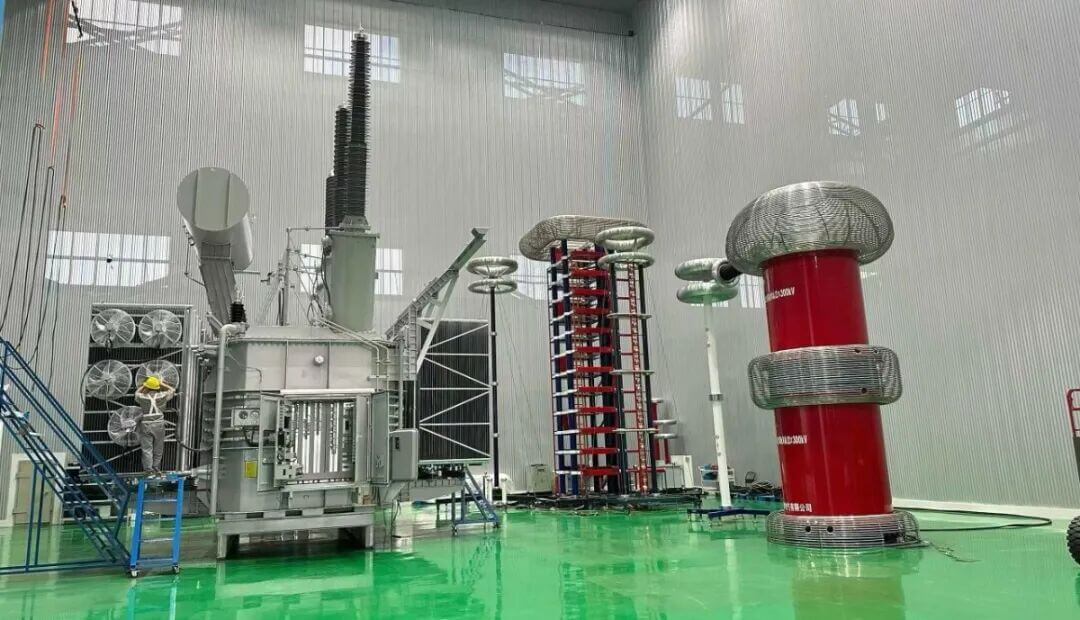
A switching impulse test is an important high-voltage transformer test used to assess whether the insulation system can withstand transient overvoltages caused by switching operations, fault clearing and other system events. It is especially relevant for transformers used in extra-high-voltage transmission and substation projects.
The test applies a specified impulse waveform to the transformer insulation system and evaluates its response under conditions that are different from normal power-frequency operation. The exact test requirements, voltage levels and acceptance criteria must always follow the approved project specification and applicable standards.
What Is a Switching Impulse Test?
A switching impulse test simulates the electrical stress associated with switching overvoltages in high-voltage networks. These overvoltages can occur during line energization, circuit-breaker operation, fault clearing, load rejection and other changes in power-system operating conditions.
Unlike a continuous 50Hz power-frequency test, a switching impulse is a short-duration transient voltage with a specified waveform. The insulation system must withstand this transient stress without insulation breakdown, abnormal discharge or other evidence of failure.
For transformers with high voltage ratings, the test can provide valuable information about insulation coordination in areas such as windings, leads, terminals, oil gaps and other critical insulation structures.
1. Why a Switching Impulse Test Matters
High-voltage transformer insulation is exposed to different types of electrical stress during its service life. Power-frequency voltage, lightning impulse voltage and switching impulse voltage do not affect insulation in exactly the same way.
A switching impulse test is used when the project specification requires verification of transformer performance under switching-overvoltage conditions. It helps confirm that the insulation design is suitable for the expected operating environment.
The test is particularly important because switching transients can create different voltage distributions within the transformer compared with normal 50Hz operation. These stresses may affect winding sections, line ends, neutral points and long insulation gaps in different ways.
- It evaluates insulation performance under transient overvoltage conditions.
- It supports verification of winding and lead insulation coordination.
- It helps identify possible weaknesses before equipment is delivered to site.
- It provides documented test results for customers, consultants and project owners.
2. Switching Impulse Test vs. Power-Frequency Withstand Test
A power-frequency withstand test and a switching impulse test are both used to evaluate transformer insulation, but they apply different voltage waveforms and represent different electrical stresses.
Power-Frequency Withstand Test
A power-frequency test applies an alternating voltage at the system frequency, usually 50Hz or 60Hz, for a defined duration. It is commonly used to verify insulation performance under specified AC test conditions.
Switching Impulse Test
A switching impulse test applies a short-duration impulse waveform intended to represent switching-overvoltage stress. The waveform, peak voltage, timing and sequence are defined by the applicable standard or customer technical specification.
One test should not automatically be considered a substitute for the other. The required test scope depends on transformer voltage class, insulation level, grid conditions, customer requirements and the relevant standard.
3. Key Insulation Areas Evaluated During Testing
During a switching impulse test, the transformer insulation system is assessed as a complete electrical structure. Test engineers pay close attention to areas where electric-field stress may be concentrated.
- High-voltage winding line-end insulation
- Inter-winding and inter-phase insulation
- Neutral-point and terminal insulation
- Transformer leads and connection structures
- Oil gaps and oil-paper insulation systems
- Bushing and external-terminal coordination
Transformer design must consider these areas during the engineering stage. The winding configuration, shielding arrangement, insulation material selection and lead structure all influence the distribution of electrical stress.
For a high-voltage project, insulation design should be reviewed together with the system study, grounding method, protection arrangement and specified test requirements.
4. Typical Switching Impulse Test Procedure
The exact procedure varies according to the transformer design and approved test specification. However, a typical switching impulse test includes several controlled steps performed in a factory test environment.
- Review the approved test plan, transformer rating and required waveform.
- Prepare the transformer, test circuit, measuring instruments and safety system.
- Confirm correct connections, grounding and test-equipment calibration.
- Apply reference impulses according to the approved procedure.
- Apply the required full-voltage switching impulses to the specified terminals.
- Record voltage waveforms, current signals and relevant measurement data.
- Compare test results with the approved acceptance criteria.
- Complete the test record and include it in the project documentation where required.
Testing should be performed by qualified personnel using appropriate equipment and safety procedures. Customers may also require witness testing, third-party inspection or detailed test reports before shipment.
Applicable Standards and Project Requirements
Transformer testing requirements are normally determined by the contract specification, customer technical requirements and applicable standards. International projects may reference IEC, ANSI, GB or utility-specific standards.
The relevant standard should be confirmed before design approval and before factory testing begins. This is particularly important for high-voltage and extra-high-voltage equipment, where test voltage, waveform, connection method and acceptance criteria can vary by project.
For general information about international electrotechnical standards, visit the International Electrotechnical Commission. For high-voltage transformer solutions that may require advanced insulation testing, see our 345kV fully insulated transformer solution.
How Yawei Supports Transformer Test Documentation
Yawei Transformer supports customers with project-specific transformer testing, technical documentation and factory inspection coordination. The scope of testing is confirmed according to the transformer design and the approved technical specification.
For projects requiring power transformers, EHV transformers or customized insulation designs, customers can provide the voltage level, capacity, applicable standard, test requirements and destination-market details for technical review.
Explore our full transformer product range or learn about transformer applications in solar and wind power projects.
Conclusion
A switching impulse test is an essential part of the quality-verification process when it is required for high-voltage transformer projects. It evaluates insulation performance under short-duration transient overvoltage conditions that differ from normal power-frequency operation.
By confirming test requirements early and completing the approved factory test procedure, project owners can gain greater confidence in transformer insulation performance before delivery and site commissioning.
 English
  Spanish
  Arabic
  French