This paper discusses main transformer winding deformation fault diagnosis based on a practical substation main transformer tripping accident.
1. Fault Phenomenon
During the operation of the main transformer in a substation, the heavy and light gas protections of the transformer body acted successively, the three-side switches of the equipment tripped, and the main transformer was out of service.
2. Fault Diagnosis and Analysis
Power transformers operate with high stability under normal conditions, but outlet short-circuit is one of the main causes of transformer faults, with frequent fault cases of transformers induced by outlet short-circuits every year. When a transformer suffers from an abrupt short-circuit fault, the damage degree is closely related to the short-circuit current magnitude and the operating efficiency of relay protection. If the short-circuit current is small, the relay protection can quickly operate to isolate the fault, causing slight damage to the transformer windings. In contrast, a large short-circuit current or delayed operation/blocking of relay protection will impose severe impact on the transformer windings, and even lead to direct equipment damage.
The huge electrodynamic force generated by short-circuit current causes mechanical vibration of the transformer, loosens the winding clamping structure, and may further result in structural damage to windings with long-term operation. With the continuous growth of the installed capacity of the power system, the system short-circuit capacity keeps increasing, leading to a rising trend in transformer winding deformation faults after outlet short-circuits. The condition evaluation and re-operation feasibility judgment of transformers after sudden short-circuits are key decision-making tasks for power operation departments. In accordance with the relevant codes for routine tests of power equipment, transformers with outlet short-circuit faults shall undergo a series of special tests including dissolved gas analysis in oil, winding DC resistance test, short-circuit impedance test, winding frequency response test, as well as no-load current and loss test to fully eliminate potential equipment hazards.
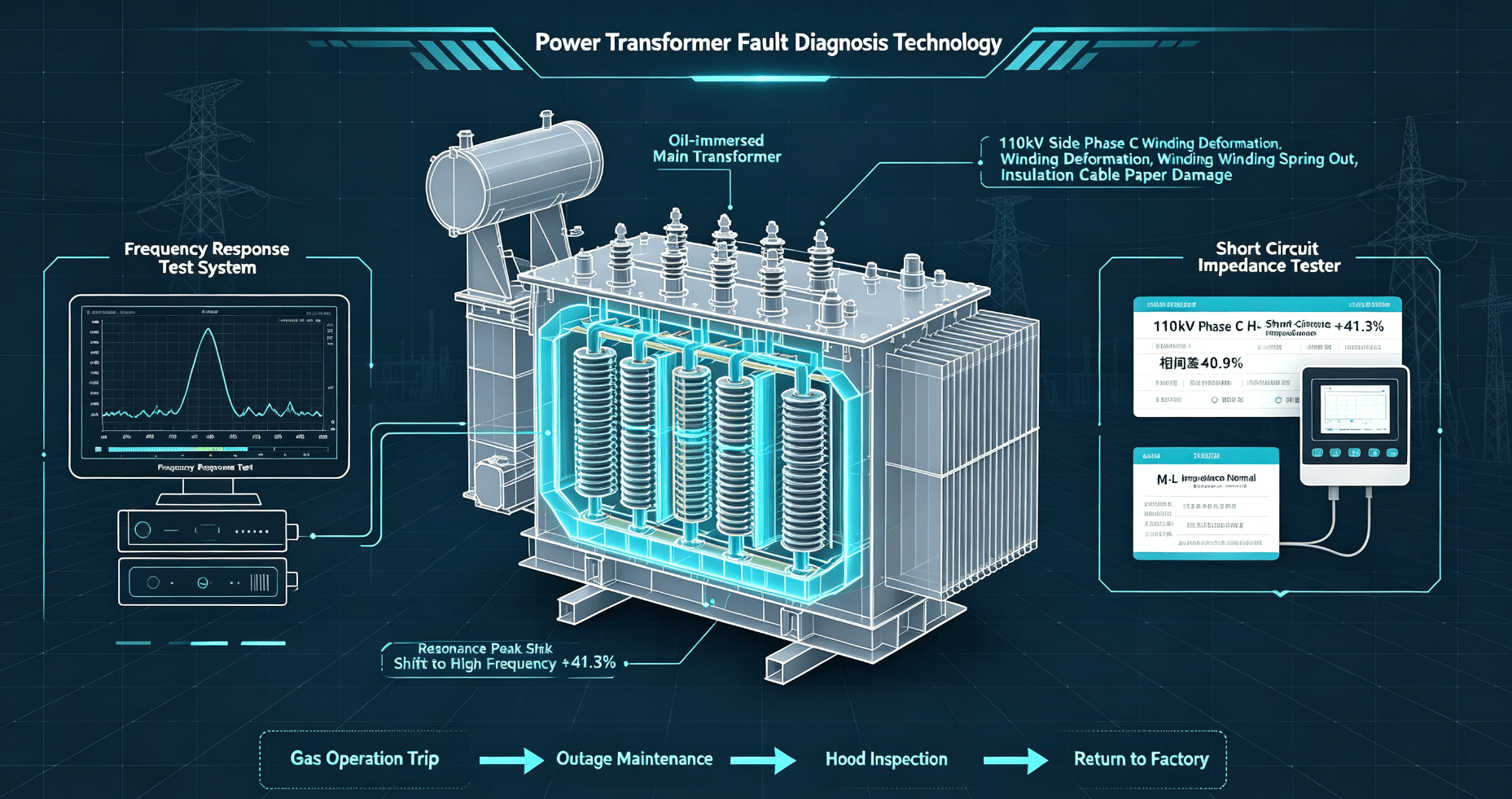
In this fault case, the frequency response method and short-circuit impedance method were adopted for winding deformation diagnosis, with a dedicated transformer winding deformation frequency response test system and transformer short-circuit impedance tester for on-site detection. The test results show that the characteristic peak of the winding frequency response curve shifted to the high-frequency direction with a significantly increased spectrum amplitude. The high-low voltage short-circuit impedance of phase C on the 110kV side increased by 41.3% compared with the previous pre-test data, and the phase-to-phase difference reached 40.9%, while the medium-low voltage short-circuit impedance of the same phase was normal. According to the code specification, the allowable variation limit of reactance of concentric circular transformer windings before and after short-circuit current impact is no more than 2%. The test data far exceeds the standard limit, confirming that severe winding deformation occurred in phase C on the 110kV side of the main transformer, and hood-lifting inspection shall be carried out immediately.
3. Overall Safety Measures
Implement full power outage of the faulty main transformer, and carry out power-off maintenance and hidden danger investigation.
4. Fault Treatment Procedures
After hood-lifting inspection, it was found that the main transformer coils were not tightly wound. The outermost turn of the first bottom cake winding popped out under the electrodynamic force of short-circuit and contacted the coil shielding screen. During equipment operation, the continuous vibration of the transformer caused long-term friction between the winding turn and the shielding screen, eventually damaging the cable paper insulation on the outer surface of the winding turn. Considering the damage degree of the equipment, the main transformer is recommended to be returned to the factory for in-depth maintenance.
5. Conclusions and Operation & Maintenance Suggestions
Transformer hood-lifting inspection is a maintenance work consuming massive human and material resources. To avoid misjudgment and missed judgment of faults, the combined application of the frequency response method and short-circuit impedance method is an efficient and reliable means to accurately diagnose transformer winding deformation. Based on the experience of this fault disposal, optimized operation and maintenance suggestions are put forward as follows: first, special winding deformation tests shall be conducted for all newly-built and-to-be commissioned main transformers before commissioning to retain original benchmark data for subsequent state comparison; second, for in-service main transformers, regular winding deformation tests shall be carried out combined with routine maintenance and fault investigation to establish complete equipment test files.
For transformers suffering from outlet or near-area short-circuit faults, special winding deformation detection must be implemented to accurately evaluate the winding state and confirm the re-operation condition, even if the results of conventional electrical tests and oil tests are qualified. In the diagnosis of winding deformation, multiple dimensional data including resonance point offset, correlation coefficient and short-circuit impedance variation shall be comprehensively analyzed to avoid judgment errors caused by single data. Meanwhile, it is necessary to continuously accumulate transformer test data under various working conditions, summarize fault judgment rules, improve the accuracy of winding deformation fault identification, and ensure the safe and stable operation of power grid equipment.
 English
  Spanish
  Arabic
  French