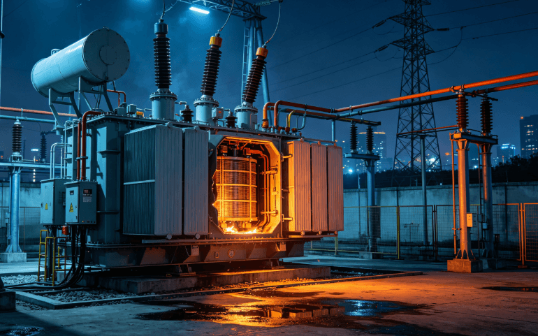
This paper analyzes a typical 110kV main transformer 35kV user side outlet short‑circuit fault occurred in substation. We describe the fault phenomenon, locate the root cause, and summarize effective countermeasures for power transformer operation maintenance.
I. Basic Failure Information
- Substation Site: 110kV Independent Substation
- Faulty Equipment: #2 Main Transformer, Model SFSZ8‑40000/110
- Failure Trigger: Outlet short‑circuit on the 35kV dedicated‑line user side; the fault point is only 1.1 km away from the substation
- Protection Operation: Differential relay of #2 main transformer operated, heavy gas protection operated; 35kV outgoing line Circuit‑Breaker 59 tripped by instantaneous overcurrent protection; three‑side switches of the main transformer tripped and the unit was out of service
- Equipment History: A full‑station voltage‑loss incident caused by 35kV line over‑tripping short‑circuit occurred in a certain year. Conventional test data showed no abnormality afterwards, and no in‑depth winding deformation test was performed.
II. Complete Failure Process
At 22:37 on August 19, equipment failure occurred at the 35kV dedicated‑line user end of this substation, resulting in inter‑phase outlet short‑circuit. The fault current impacted #2 main transformer. Heavy gas protection and differential protection of #2 main transformer in‑station operated simultaneously, and Circuit‑Breaker 59 on 35kV side tripped by instantaneous overcurrent protection. Combustible peculiar‑smell gas was detected inside the gas relay. The main transformer was immediately isolated and taken out of service. After the failure, conventional power‑off tests were carried out. Multiple sets of data presented abnormalities, which determined severe internal winding defects. Arrangements were made for factory‑return disassembly inspection.
III. Failure Test and Disassembly Inspection Results
1. Power‑Off Electrical Tests
- DC Resistance: Inter‑phase difference of 35kV side Phase B reached 1.25%, with obvious variation compared with previous pre‑test data.
- Winding Deformation Test: The frequency‑response curve of 35kV Phase B showed large deviation against historical data and Phase A / Phase C; winding deformation was confirmed.
- Induced Withstand Voltage Test: Loss of Phase B greatly exceeded standard value, indicating severe internal defects.
- Oil Chromatography Analysis: Acetylene and total hydrocarbon values seriously exceeded limits. Three‑ratio method diagnosis indicated high‑energy discharge fault.
2. Disassembly Inspection Findings
- Low‑voltage winding: No obvious deformation in appearance; slight insulation coking at the position corresponding to medium‑voltage fault location.
- Medium‑voltage Phase A: 7 dents and deformations of varying degrees, maximum depth 42 mm.
- Medium‑voltage Phase B: Large‑area severe deformation; short‑circuit burnout of transposed conductors at cake 47‑50; discharge traces observed on medium‑low‑voltage surrounding plates.
- Medium‑voltage Phase C: Slight concave‑convex deformation.
- Overall device body: Spacers offset and loosened; winding clamping structure loosened.
IV. Failure Causes
- Direct inducement: Near‑range outlet short‑circuit on 35kV user side with short‑circuit capacity of 261 MVA. Huge electrodynamic force generated impact on windings.
- Inherent design defect: Medium‑voltage regulating winding and main winding share the same iron‑core leg, resulting in unbalanced ampere‑turns. Large force difference among different coil cakes under short‑circuit condition, leading to high deformation risk.
- Manufacturing process deficiency: Loose coil winding; high‑strength self‑bonding conductors not adopted. The overall short‑circuit dynamic‑stability performance of windings is relatively low. Although theoretical short‑circuit‑capacity parameters meet requirements upon factory delivery, actual dynamic‑stability margin is insufficient, and equipment gets damaged after enduring near‑range short‑circuit.
- Operation‑and‑maintenance deficiency: Only conventional tests were performed after historical short‑circuit impacts, without special winding‑deformation detection. Recessive winding deformation and spacer‑loosening hidden dangers were not detected in advance. Accumulated multiple impacts aggravated equipment deterioration.
V. Existing Problems
- In the early‑stage equipment bidding and supervision‑manufacturing phase, key check on winding ampere‑turn balance and short‑circuit dynamic‑stability indicators was missing. Old‑type transformers bear multiple inherent defects.
- Poor implementation of test standards after near‑short‑circuit faults; lack of in‑depth diagnosis procedures covering winding deformation and oil chromatography.
- Insufficient supervision over dedicated‑line user‑side equipment. Inadequate user‑equipment maintenance frequently causes substation outlet short‑circuits.
- No regular special hidden‑danger investigation mechanism for old main transformers. Annual pre‑tests alone cannot detect recessive mechanical damage of windings.
VI. Rectification and Preventive Measures
- New‑equipment type‑selection control: Prioritize products with independent regulating windings and semi‑hard self‑bonding transposed conductors. Clarify requirements for winding clamping force and spacer density in technical agreements. Require manufacturers to provide short‑circuit‑resistance check reports; conduct sampling sudden‑short‑circuit tests when necessary.
- Governance of in‑service old transformers: Carry out special general survey for transformers of the same type manufactured in the 1990s. Replace high‑strength windings, spring pressure studs and high‑density spacers combined with overhaul. Install 35kV current‑limiting reactors at substations with large short‑circuit capacity.
- Post‑fault test management: After transformers suffer short‑circuit impacts, mandatory full‑set tests including oil chromatography, frequency‑response winding‑deformation test and DC‑resistance test shall be performed. Conduct hanging‑bell‑jar inspection or factory‑return disassembly immediately in case of abnormal data.
- User‑side equipment control: Launch inspection on all 35kV dedicated‑line user‑side equipment. Require users to complete protection verification and preventive tests every year, and improve rapid‑fault‑clearing devices to reduce outlet‑short‑circuit probability.
- Optimization of operation and maintenance: Increase oil‑chromatography sampling frequency; take samples quarterly for substations supporting high‑energy‑consumption users. Shorten pre‑test cycle for transformers subjected to historical short‑circuit impacts, so as to eliminate winding‑loosening hidden dangers in a timely manner.
 English
  Spanish
  Arabic
  French