
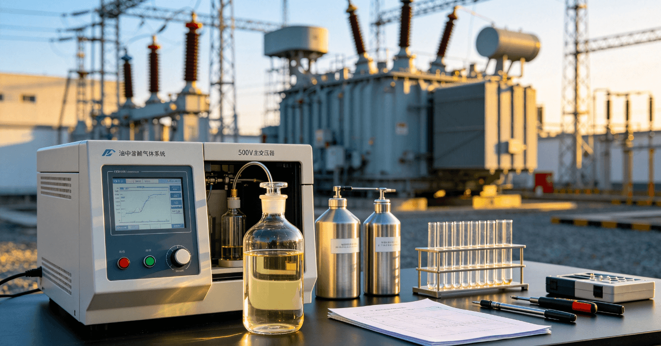
This case focuses on a 500kV substation main transformer oil chromatography acetylene abnormality found in Phase B of No.1 Main Transformer. The abnormal dissolved gas was detected during preventive maintenance tests, indicating a potential transformer internal overheating or discharge risk that required immediate inspection and monitoring.
I. Equipment Parameters
The faulty equipment is Phase B of No.1 Main Transformer at a 500kV Substation. Key parameters are listed below:
- Equipment Name: No.1 Main Transformer, Phase B
- Model: SUB
- Manufacturing Date: 2004
- Rated Capacity: 334/334/100 MVA
- Rated Voltage Ratio: 525/242/34.5
- Rated Current: 1102/2391/2899 A
- Voltage Regulation Mode: Off-circuit Tap Changer (OCTC)
II. Equipment Fault Description
The defect was discovered during preventive maintenance tests on No.1 Main Transformer carried out by the chemistry team under clear weather conditions, with ambient temperature of 28°C and relative humidity of 54%. Abnormal oil chromatography data was detected on Phase B. Compared with test results obtained on 24 May, the concentrations of acetylene (0.39 μL/L), methane, ethylene and total combustible hydrocarbons in transformer oil increased significantly. The relative gas generation rate of total hydrocarbons reached 79.44%, far exceeding the alarm threshold of 10% specified in relevant codes.
The transformer operated under relatively high load during the abnormal period. The maximum operating load hit 902 MW at 16:00 on 21 June. Long-term heavy load operation served as one of the contributing factors to the abnormal condition.
220kV System Operating Configuration on 6 August
The 220kV busbars adopt the “1+3” split operation scheme:
- Busbar I: Connected to No.1 Main Transformer, Guancheng Jia & Yi Lines, Guanda Jia Line
- Busbar II: Connected to No.2 Main Transformer, No.2 Main Transformer, Guanbei Jia & Yi Lines, Guanhe Jia & Yi Lines, Guanda Yi Line
- Busbar V: Connected to No.3 Main Transformer, Guanxin Jia Line, Guanjing Jia Line, Guanshui Jia Line (circuit breaker in hot standby status, line energized at remote terminal), Guanpeng Jia Line
- Busbar VI: Connected to No.4 Main Transformer, Guanxin Yi Line, Guanjing Yi Line, Guanshui Yi Line (circuit breaker in hot standby status, line energized at remote terminal), Guanpeng Yi Line
Operating status of switchgear: Bus tie circuit breaker 2056 and section circuit breaker 2026 are in service; bus tie circuit breaker 2012 and section circuit breaker 2015 are on hot standby. It shall be emphasized that 220kV Busbar I can form a closed-loop operation with Busbars II, V and VI via Guanda Jia & Yi Lines.
III. Fault Analysis
1. Preliminary Cause Analysis
Combining field test data and technical opinions from the equipment manufacturer, the detection of acetylene in oil of Phase B of No.1 Main Transformer is primarily attributed to internal metallic overheating. Six potential root causes are initially screened:
- Tip structures inside the equipment trigger flashover discharge during operation, decomposing insulating oil and generating acetylene.
- Metallic impurities mixed in transformer oil induce impurity discharge under strong electromagnetic field, producing acetylene.
- Hidden overheating defects exist at connection points including internal lead joints and off-circuit tap changer taps of the main transformer, resulting in oil decomposition and gas generation.
- Sparking discharge occurs on metal components such as internal tension nuts and screw rods with potential differences, generating acetylene.
- Long-term heavy-load operation and unbalanced interphase load & voltage cause core magnetic saturation and overheating, leading to decomposition of insulating oil.
- Friction of bearings and high-speed rotation of impellers inside oil pumps cause instantaneous metallic overheating, triggering gas generation in oil.
2. Power-OFF Inspection, Testing and Result Analysis
(1) Tracking Monitoring of Oil Chromatography
All historical oil chromatography data of Phase B of No.1 Main Transformer up to and including 24 May were qualified without anomalies. After abnormal gas generation was identified during the preventive test, special continuous tracking monitoring of dissolved gas components and concentrations in insulating oil was implemented on site.
(2) Special Power-OFF Inspection and Testing
To strictly control power grid operational risks and identify hidden equipment defects, a special test working group consisting of over 40 personnel carried out comprehensive power-off inspection and testing on No.1 Main Transformer from 7 September to 8 September. Major test items covered: DC winding resistance test; winding insulation resistance & polarization index test; dielectric loss and capacitance measurement of windings and bushings; insulation resistance test of core and clamping frames; winding deformation test; oil chromatography test on Phase B insulating oil; long-duration induced voltage test (partial discharge test); oil pump starting current test.
Comparative analysis with historical test data shows that all routine electrical test parameters maintain stable trends and comply with standard specifications without abnormal deviations. Tracked oil chromatography data of Phase B remains stable, with no continuous growth of dissolved gas and steady acetylene concentration. The long-duration induced voltage and partial discharge test show no abnormalities and yield qualified results. The starting current of oil pumps is within normal range, which completely rules out the possibility of gas generation caused by friction overheating of oil pumps. Overall test results verify that all performance indicators of three phases of No.1 Main Transformer are normal, and no structural or electrical defects are detected.
(3) Comprehensive Conclusion from Test Evaluation
Based on online monitoring data (8 August – 6 September) and power-off test results obtained on 7 September, the manufacturer conducted dedicated technical analysis: Under normal conditions, acetylene is mainly produced by arc discharge or metallic overheating inside transformers. In the event of arc discharge faults, hydrogen content in oil will rise sharply simultaneously. However, monitoring data indicates low and stable hydrogen concentration, which basically excludes arc discharge failure.
Meanwhile, trace ethylene detected in oil indicates characteristics of metallic overheating. Nevertheless, the CO/CO₂ ratio exceeds 3, which contradicts the typical signature of sustained metallic overheating faults. It is comprehensively judged that the acetylene detected in oil stems from accidental transient factors, rather than sustained internal defects of the equipment.
After professional maintenance evaluation, two potential triggering factors are finalized: ① Instantaneous discharge and gas generation caused by metallic impurities in transformer oil under strong electromagnetic field; ② Trace gas generation induced by temporary metallic friction overheating during oil pump operation.
IV. Reference Cases of Similar Equipment
No.2 Main Transformer at this substation is of the same model and batch as No.1 Main Transformer, serving as a highly valuable reference. On 10 December, acetylene at 0.26 μL/L was detected in Phase A of No.2 Main Transformer during preventive testing. Continuous online monitoring and periodic oil chromatography tracking were immediately arranged. Subsequent data revealed gradual decline of acetylene, and acetylene was no longer detectable after 5 December the same year, with the equipment returning to normal operation automatically. This case proves that sporadic trace gas generation on identical equipment has the possibility of self-recovery without persistent fault risks.
V. Preventive Measures and Disposal Scheme
Specialized measures for operational control, condition monitoring and maintenance are formulated in accordance with test data, fault analysis conclusions and operating experience of similar equipment:
- Load Control No.1 Main Transformer is allowed to be reconnected to the grid. Strict load control shall be enforced, with maximum operating load limited to 850 MVA to avoid abnormal equipment conditions triggered by heavy-load operation.
- Full-Cycle Condition Monitoring Dedicated personnel are assigned for continuous monitoring and regular analysis of online oil chromatography data. Enhanced routine patrol and infrared temperature measurement shall be implemented. Phased monitoring requirements are specified as follows: ① Before 15 September: Offline oil chromatography testing twice weekly; infrared temperature measurement, core earth current test, online oil chromatography monitoring, load and winding temperature monitoring once daily. Monitoring data shall be summarized and submitted to the Equipment Department every day. ② 16 September – 30 September: Infrared temperature measurement, core earth current test and offline oil chromatography testing once weekly; continuous daily monitoring of online chromatography, load and equipment temperature. Weekly data summary to the Equipment Department. ③ 30 September until completion of equipment replacement: Infrared temperature measurement, core earth current test and offline oil chromatography testing once every two weeks; routine daily online monitoring. Biweekly data summary submitted to the Equipment Department. The Equipment Department may dynamically adjust monitoring intervals subject to equipment operating conditions. ④ Professional technicians shall analyze monitoring data periodically to continuously evaluate the operational health status of Phase B of No.1 Main Transformer.
- Maintenance and Replacement Plan The transformer can operate stably for a long time provided no obvious fluctuations appear in monitoring data. Subject to successful overhaul of the original Phase B unit of No.1 Main Transformer, a power-outage replacement will be scheduled. All relevant works shall be completed by 30 June 2014, and the repaired unit will be reserved as standby transformer inside the substation.
- Emergency Response Plan If obvious abnormal variations are observed in subsequent monitoring including oil chromatography data, equipment temperature or electrical parameters, the emergency response procedure shall be activated immediately. No.1 Main Transformer shall be switched to standby status as soon as practicable, and the defective unit shall be taken out of service.
 English
  Spanish
  Arabic
  French